Saturday, November 29, 2014

Foundry Furnace Progress (or lack thereof...)

My goal for the Thanksgiving break was to get the furnace built that I will be using to melt the aluminum.  Unfortunately, I came down with a flu-like illness at the beginning of the week which turned my expected two additional days of progress into one sick day from work (Wednesday) and two days doing little more than moaning and laying on the couch (Thursday and Friday).  Saturday was the first day I even remotely felt like doing anything and, even then, I still wasn't anywhere near 100%.

Like the PCB etching, my design for the foundry is based on several different sources on the Internet including several Instructables.  It will be a gas fired furnace (Propane) and I will be making it out of, what else, an old Propane tank.

I've had this tank for a while and have been specifically saving it for use for a project like this.  I'm not sure where it came from.  The person I bought my house from left it behind with an old grill.  It's been empty since I've had it but, to be extra sure, I connected the tank to the grill and tried to burn off any remaining fuel.  I then opened the valve and left it upside down (since Propane is heavier than air) for over a week.

I tried to remove the valve before beginning but, even with the biggest cheater bar, all I did was bend up the top handle of the tank and round off the edges of the valve.  It didn't occur to me to use heat to loosen the locking compound they use on the threads.  Again, I still wasn't feeling 100%.  I figure I'll just deal with the valve later since I'm cutting that part out anyway.

Even though I was reasonably certain that the tank was empty, I didn't want to just jump in with the angle grinder and cutoff disk.  As part of my design for the furnace (and borrowed from several others on the Internet), I will be using sheet metal screws through the side to give the refractory cement something to grip along the walls.  I figured it'd be easier to drill the pilot holes for the screws while the tank was intact if for nothing else than to keep from ovalizing the tank while drilling.  This, if done carefully, would also allow me one final test to ensure the tank was empty before letting sparks fly. 

I marked out the drilling locations evenly as well as the cut line for the top.  Using a center punch, I marked my first drill location.  With some cutting fluid and a sharp drill bit, I very slowly started to drill through the tank.  Again, I was confident the tank was empty but it was still a little unnerving to be drilling into a Propane tank.  I went slowly to lessen the risk of creating a spark.  When it finally pierced the tank, there was no sudden rush of gas and, more importantly, no kaboom.  I then proceeded to drill the remaining pilot holes.  Once complete, I set the tank out in the middle of the driveway for a bit to let any residual gas dissipate before cutting.

Well I couldn't put it off any longer, it was time to cut.   

<EDIT/UPDATE!!!> I now know I should have removed the valve and filled the tank with water to properly and safely displace any gas before cutting.  Lesson learned and fortunately I didn't blow myself up doing this.  I will re-iterate, this blog is not a how-to guide, it's a "how I did it" guide.  I will most certainly do some stupid things on here and, if you are stupid enough to follow without checking for yourself, that's on you. </UPDATE> 

Using an angle grinder with a cutoff disk, I slowly worked my way around the line marked.  I found the easiest way was to lay the tank on its side (cradled with some scrap 2x4s to prevent rolling) and make small cuts.  I'd cut a couple of inches, then rotate the tank, cut, rotate, cut, rotate... to allow me to ensure the cut was a straight as possible.  The unevenness isn't near as bad as it seems in the picture and will easily clean up with a file.  The most important thing (to me) was that it wasn't lopsided or overly wavy.  


As this is a standard propane tank, the diameter is 12 inches.  Since I plan to have the cement walls 2 inches, I need to find a good cylindrical form, close to 8 inches in diameter, to use for the inner part of the concrete mold.  I'll be keeping my eye out for something to use or, worst case, I'll bend something out of sheet metal.

That's about it for today.  I intended to bend up the round bar I'll be using for legs as well as making additional cuts to the top which will ultimately become the lid, but I'm starting to feel pretty puny.  Time to go back inside and resume my spot on the couch.


Tuesday, November 25, 2014

Finishing up the Form

In order to eliminate as much additional finishing as possible on the cast part, as well as to aid in the mold creation, I decided I should smooth out the ridges that were created as a result of using multiple layers building the form.

Using wood filler, I filled in the transitions between layers and also some gaps left during the initial glue up.


After drying, it was sanded smooth and shellacked.  The form, not me.... (Okay, I probably was a little shellacked at the time too.)


Hopefully, this will make forming the mold much easier as well as prevent a lot of finish work on the casting.

Saturday, November 22, 2014

The PCB Part 2: Transferring the Layout and Etching

As mentioned previously, I'm using the toner transfer method to create my PCB.  I've read a lot of methods that used Inkjet printer photo paper as well as some people who have had success using glossy magazine pages, both printed using a laser printer.

I decided to try both since I already had the photo paper but, in the future it would be nice if the magazine pages work since I have plenty of those around.


The bits....
The board trimmed to size, scuffed with Scotch-Brite and the iron ready to go.

Attempt #1 with the photo paper, not much of the layout transferred.

Attempt #2 with the magazine paper.  I believe this piece came from a catalog I received in the mail.  A little more transfer but again, not complete.

Attempt #3, back to the photo paper.  This one seemed more promising as I actually had to soak the photo paper to remove it.  But, after doing so, it was better but it still wasn't a complete transfer.

I'm too drunk and/or tired to mess with this any more tonight.  I have a couple of theories about what may be wrong (other than the obvious).  First, several of the articles refer to setting the laser printer to use maximum/darkest toner setting.  The one I'm using doesn't allow that option so I'm stuck with the standard amount.  Second, and most likely, I'm not being patient enough when heating the paper with the iron.  I'm probably moving the iron too soon and not being careful enough with overlaps which may be leading to the gaps I'm seeing in the transfer.

I'll try again at a later date.

Friday, November 21, 2014

The PCB Part 1: Layout

Along with preparing the form for casting, I've been working on the electronic side.  As mentioned, I plan to go with LEDs.  Rather than using a typical project board to lay them out, which would require a much more soldering as well as cutting/stripping way too many jumper wires, I figure I'd go for a custom PCB.  

Since this is truly a one-off PCB, it doesn't make sense to send it out to be made.  Even one of the discount makers, with the required order minimums, isn't cost effective.  

Plus, I've been wanting to try to etch my own PCBs for a while using the toner transfer method. I'm following advice from several methods from the Internet but I'm sticking closest to the write up on the Robot Platform website.

The first step is to create the layout.  I came across this really neat layout program called Copper Connection written by David Cook.  It is an excellent little program!  It doesn't have the advanced features  (such as auto-routing, circuit analysis, etc...) that some other packages may have but it is exceptionally simple to use.  And for this project, it was perfect!  I highly recommend it, check it out at Mr. Cook's website Robot Room.

After a few minutes to get up to speed, and one revision change after deciding to use a different type of LED, I was able to layout This circuit will include the tail lamp (i.e. the light that is on when the headlight is on) and the stop lamp (aka brake light).  I wanted to incorporate turn signals as well but felt that would be too complicated for a single-sided PCB.  

Here's a quick shot of the layout showing the top silk screen (which won't be used in the final PCB) and the bottom copper layer.  


Keep in mind, the bottom layer needs to be backwards because it will be transferred to the actual PCB.  One of the great features of Copper Connection is that it allows you to layout a component as a stack on all layers at once.  Then, when it comes time to print the PCB, depending on your selected transfer method, it flips the appropriate layers as needed.  This is especially useful after having a few beers, when your spacial orientation ability is not where it should be.

Thursday, November 20, 2014

Form finally fully glued!

Got the form glued together... now to get the forge and casting setup ready!
If I'm going to cast the housing, I need a form to make the mold... now how to do that? Well, I have access to a laser cutter, why don't I break it into layers. 

Throw some melamine into the machine and here's the bits I ended up with:  

I meant to have more pictures in between but I got so excited after they started popping out, I forgot. Layers of each, glued together should give me my final form.

Monday, November 17, 2014

Talked with a TechShop regular after my last post about my options. After our discussion, I think I might try my hand at something else I've been interested in: casting!

I swear this isn't a TS commercial but that's one of my favorite things about the place. I can chat up someone and get new and different ideas about where to go next.

Sunday, November 16, 2014

What to do about the housing.... There has to be something that encloses the electronics and LEDs. My first thought was sheet metal and it's definitely a skill where I need improvement. So I spent a few hours on Sunday at TechShop getting started where I made a buck out of good quality plywood.  

After piddling with it for a bit, I realized this definitely is not going to work.  As small as it is I'd need to section it, especially on the internal bends.  In addition, the tightness of the joints, there is no way I have the skills (or will in a reasonable amount of time) to weld it back together.

Need to step back....

Wednesday, November 12, 2014

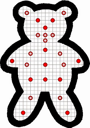
Well, if it's going to be a tail light like this, it's got to be LED. Not that I think it has to incorporate a new fangled component, but due to the shape. There's really no other choice for it to work correctly. So here's my initial layout. The solid red circles are the running lights, the red rings will be the actual brake light.


I also toyed with the idea of incorporating turn signals but, with keeping in mind that this is supposed to be a "home brew" project, that was definitely a no-go. I drew up several different ways but all required multi-layer PCBs.   

This layout is going to be restricted to what I can do at home. Sure, I know lots of places where I can have a multi-layer board manufactured but, again, home brew.

Monday, November 10, 2014

THE CHALLENGE

THE CHALLENGE: build something with this guy!

So I've been sitting on this li'l guy for a few weeks, thinking about what I want to do with it.  It's a little cast iron piece I picked it up at a local motorcycle swap meet.  I bought it from this really cool dude who admitted he generally brings one random piece to such meets to see who buys it.

Well, I'm that dork.  Initially, I thought it might be cool welded into a sissy bar or something.  It set on the shelf and after staring at it for a bit, I think it'd make a really cool bezel for a tail light.  That's going to take a lot of different disciplines to pull this together, many of which I don't currently possess, but that's why it's "THE CHALLENGE".