Wednesday, December 31, 2014

More Muffins with a Side of Greensand

There hasn't been much post-worthy lately but I have made a little bit of progress on my casting projects. The holidays have been fairly busy and it seems like the days where I don't have anywhere I'm supposed to be, it's been cold and spitting rain so I still couldn't work on any of it.

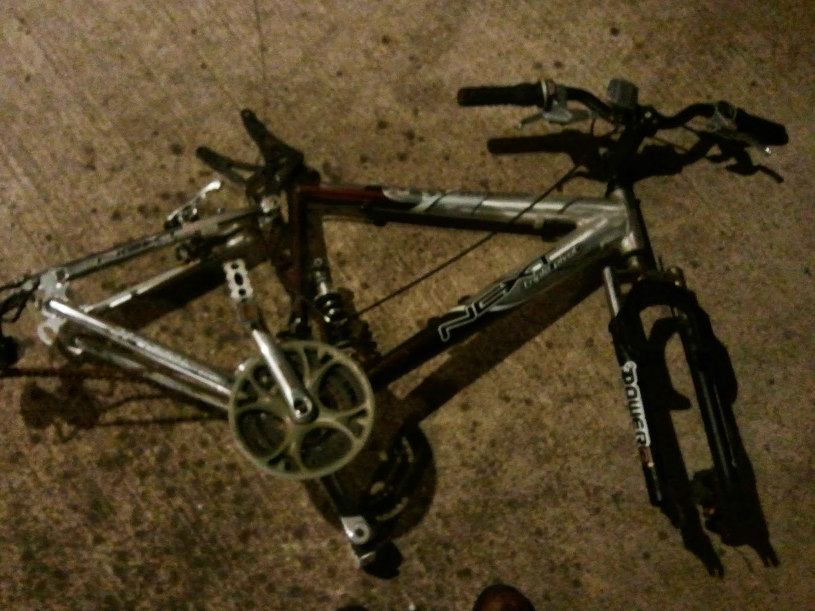
I managed to melt the rest of the bike pieces and a few other items and now I'm just shy of a dozen aluminum muffins.
I also got the greensand ready to go. I ended up using a mix of 10% bentonite clay (by weight) and play sand with a little water based on recipes I saw on several websites and in videos. 

Initially it was having trouble finding the bentonite in either the amount I wanted (I didn't need a truck load) or in the granularity I needed (one of the big uses of it is for kitty litter which is way too coarse). 

Eventually, I learned that it is the same stuff they use in mud masks at day spas. I found a nice 2 lb container of it on Amazon that ended up being the perfect amount for what I needed.  When mixed with about 18 lbs of play sand, it was just enough to fit in a 5 gallon bucket (without compressing).

For the play sand, it was nothing special. I just used the stuff from the big box hardware store that is sold for kids sandboxes.  I did, however, screen it first using a screen I made out of some window screen I had from another project.  There was a surprising amount of small pebbles in the sand I used and I'm glad I took the time to get them out before mixing everything together.

One of the bigger tips I can pass along for anyone else trying this is to use a spray bottle to add the water. It is very easy to put in too much water and, of course, very hard to get it back out.  Okay, not hard, but it takes time waiting for it to evaporate. I can't take credit for this tip, I saw it on a couple of the websites/videos, but highly recommend doing it this way.


As far as just how wet to get it, I followed the general rule: dry enough to not stick to your hands but wet enough to stay together when squeezed. 
It also should break cleanly and not crumble. 
The resulting sand packed great. I can't wait for the weather to clear up so I can finally get around to making the mold and casting.

Friday, December 19, 2014

Baking Aluminum Muffins

It rained last night so I didn't get to try out the furnace as planned but I finally did tonight. Here's the setup. As it turns out, using the air compressor didn't really work like I had hoped. Even with the adjustable regulator there either wasn't any air flowing or way too much which would just blow the flame out.  

Instead, I made a cone out of thin sheet metal and used an old hair dryer as the blower. Even that was too much air flow. It was a balancing act of aiming the hair dryer off to the side of the opening to get just the right amount of air.


The hair dryer at its optimal spot. "Vidal Sassoon! Because, if you don't look good... it's probably because you were disfigured by molten metal while using a hair dryer as part of your sketchy furnace."

Once I did get it situated though, it really roared to life. I got my makeshift crucible up to a nice orange color and then started feeding it pieces of the bike I dismantled the other night.


Initially it didn't look like it was melting but, after a few minutes, I touched it with the tongs and it just crumbled into the crucible.


It took about 25-30 minutes for the pieces to melt completely and then it was time to pour. Sorry, no pictures of this step. My hands were full and I couldn't convince anyone else to stand anywhere close enough to my contraption to get pictures or video.


Here are the fresh baked aluminum muffins! This is approximately half of the bike peices. I'll melt the rest at a later date.

While I was doing this I was also "collecting" more aluminum.  I know everyone says your not supposed to use beer or soda cans because of the paint and interior lining.  It's probably the same people that say you shouldn't imbibe and operate 1500 degree furnaces.


Tuesday, December 16, 2014

Getting the Materials Ready to Melt

My dad found this stripped bike frame a few years ago behind his office building.  He was excited because he thought he found something that might be of value but, as you can see, it turned out to be a Walmart special.
 

Still, he asked me if I might be able to come up with the missing pieces so that he could "ride it around the neighborhood to get a little bit of exercise."  I still feel a little bad because I kind of blew him off about it.

When I cleaned out his house after he passed a couple of years ago, I just couldn't bring myself to throw it away.  Although I definitely don't need a bike, I thought I might use some pieces off it for something someday.  Well what better way to mourn and shed some guilt than at 1200 degrees?!?!

Here's the main aluminum pieces I grabbed for this: the front part of the frame, the crank arms, the rear brake arms, and the pedal cages.  The rest went back in the junk pile to possibly be used for another project.  (Spoiler alert: keep an eye out for the shock on a future project, I already have in mind what I'm going to use if for.)


The angle grinder made short work of cutting the frame into workable lengths.  Unfortunately the frame also made short work of my cheapo angle grinder.  I managed to let the magic smoke out of it so now it no-worky.  Hmmm... I wonder if there are any worthwhile aluminum or brass pieces inside?  I know there should be a fair bit of copper.

Anyway, stripping the bike and getting everything ready to fire up the furnace took a bit longer than I intended.  Unfortunately, I only had time to get everything set up before I had to call it a night.

I did manage to get the flame going for a quick check though it wasn't interesting enough (or running long enough) to warrant a pic.  I am now, however, missing the hair on my left hand.  I'm going to have to be a bit more careful when I resume tomorrow.

Shopping for Forging Supplies at... Goodwill

Or should I say, foraging for forging supplies.  Wow, that was lame.  I even embarrassed myself.  Anyway, I did quite well at Goodwill today getting some of the last few accessories I needed before I really fire up the forge (hopefully tonight!).

I managed to find quite a few stainless steel containers to use as crucibles, a pair of sturdy tongs, slotted spoon, and an old (i.e. pre-Teflon) steel muffin pan.  


I also found quite a few pieces of brass.  I'm not quite ready for that just yet (as I plan to start with aluminum) but no point not to stock up.  Especially when almost everything was $.99 or $1.99!  

I did feel like I just sacked someone's house, though, as I walked out with an armload of candlesticks and other metal pieces.  I should've bought a pillow case to sack it all up in.

Saturday, December 13, 2014

Back from the Voodoo Vintage/Old Filthy MC Swap Meet

Well, I made it back from the swap meet put on by Voodoo Vintage and the guys from Old Filthy MC.  As usual, they did not disappoint! 

Each time it gets a little bigger and this time there were several new faces and quite a few parts.  Not to mention, the OFMC guys are super laid back and a blast to hang out with!

I managed to score a couple of pieces I wanted for patterns that I may cast and/or machine at some point.


I also scored a sweetheart of a deal on a tank and tracker tail section for an XS650.  I'm not quite sure what I'll do as I don't have an XS650 (yet) but, for now, it looks really sweet hanging on the wall in the garage!


Thanks again to David at VV as well as Sin, Shags, and the rest of the guys from Old Filthy for the hospitality.  I found some cool parts, consumed a few beverages, and had a great time hanging out!  I'll definitely be out at the next one!


Second Attempt at the Burner

I don't have much time for an update, just wanted to post my results for the MKII version of the burner. I added a tee to it, another small nipple followed by a pipe cap. In the pipe cap, I drilled and tapped it to accept a male 1/4 NPT quick connect (the type you use with air tools). I then connected an adjustable pressure regulator in line and finally connected it to, you guessed it, an air compressor.


There was just enough time to test it before we had to go out for the evening.  It was much more impressive than the previous version.  While it did take some tweaking to get the air flow and gas levels correct, I was able to get the flame completely blue.  It's hard to tell from the picture (since there's nothing for a size reference) but the flame was about eight inches in length.


There still are a few minor changes I'd like to make (hence why there's still no parts list) but it's 90% there.  In particular, I'll probably replace the pipe where I initially machined the air slots.  When trying to push the burner to it's max, it had a tendency to "backfire" out of the slots when the air pressure dropped.  The second would be to add a separate shutoff valve for the air line (in addition to the pressure regulator).  The third may be to add a larger air reservoir.  It doesn't take a lot of pressure to achieve the best flame (about 5-10 PSI) but my poor little compressor was running it's heart out trying to keep up.

Friday, December 12, 2014

The Voodoo Vintage / Old Filthy MC Swap Meet


I'm a little late posting this but the next swap meet at Voodoo Vintage put on Old Filthy MC is this Saturday (12/13).  I think this may be the forth one they've held but the attendance is growing each time.  I expect tomorrows will be a fun event and there's always a good group of guys to talk to and hang out with.  More Info....

Wednesday, December 10, 2014

First Attempt at the Burner

I made a first attempt at a burner tonight. I'll post a complete parts list once I get it working the way I want. For this iteration, I tried milling some slots in the side near the gas outlet. Then I made a sleeve out of a slightly larger pipe so I could adjust the airflow as needed.


The additional air helped to make an impressive flame, but it still wasn't what I was looking for.


It's big, but not as hot as I think I'll need. I'm looking for a mostly blue flame so I think I'll have to step the design up to a forced air configuration. Back to the hardware store tomorrow for more parts....

The PCB Part 4: Drilling, Populating, and Soldering

I finally got around to finishing the PCB last night.  I didn't have any drill bits near small enough so I used some Amazon points to order this micro drill set from Amazon which included a swivel head pin vice (the "handle").  It's a pretty nice set but it only took me two holes to realize I didn't want to do the rest by hand.


It would've been best to use a small drill press, which I don't have, so I figured I'd just use a rotary tool.  I have the full Dremel kit (minus the drill press base, of course) including the pen attachment but that still seemed too bulky.  I bought one of those cheapo 80 piece rotary tool kits from Harbor Freight quite some time back.  It's nice and small, which would make it easier to keep the bit from wandering, so I thought I'd give it a try.

I planned to wrap tape around the 1mm drill bit from the Amazon kit to fit it into a collet but, low-and-behold, there is a 1mm collet as well as a 1mm drill bit in the HF kit!  This made short work of the remaining holes though it did have a tendency to walk slightly.


After drilling was complete, I used the real Dremel with the side cutting bit and the small, plastic router base to cut the PCB to shape.  This worked fairly well, so long as I went slow and kept a firm grip on the Dremel.  I used a hand file afterwards to clean up the edges.


Then, on to the soldering.  I discovered two areas following the etching process where the traces had breaks.  I addressed those while soldering but using a small jumper wire.  I also decided to "coat" the copper traces with solder.  My reasoning was to reinforce them, in case any others were marginal, as well as to provide a little corrosion resistance.  It looks ugly as hell but it works.


For the wired leads, I went with standard Yamaha colors (at least for circa 1980): Black = Ground, Blue = Indicator, Yellow = Brake.

The LEDs were purchased online from superbrightleds.com.  Their pricing was reasonable and they were shipped extremely quickly.  You can find cheaper LEDs from Asia on eBay but I was quite pleased with my order from these guys.  As an added bonus, the box they shipped in, although over-sized for the 50 LEDs I order, ended up being a perfect size to carry around the various parts of the light (including the housing pattern/form) while I work on them.

Each section of the light (indicator and brake) consists of three parallel strings of four LEDs and one resistor.  I calculated the required resistor for each to be 260 Ohm but, with 270 Ohm being the closest standard size, I went with that.  (Okay, okay... I didn't exactly calculate the size at first.  I used an online calculator but I did go back and confirm it mathematically, just to make sure I remembered how to do so.)  I also found I only had five of the six required 270 Ohm resistors so I had to put two 560 Ohm resistors in parallel to get it back down to the required resistance.  Good ol' Ohm's Law!

And best of all, I got the circuit correct on the first attempt!! Alright, not exactly the first attempt.  This actually was version 1.1 where I switched from standard 5mm "dome" LEDs to the four conductor flat mount type.  In doing so, I did find that I had placed one of the LEDs backwards in the circuit which was remedied in this version.  Either way, we have light!!

Indicator/Tail LampBrake LightBoth Circuits


Lessons learned/things I'd do different next time:
  • Using overhead transparencies instead of photo paper was definitely the way to go.
  • I'd make the traces thicker as well as the component pads.  This would help in the etching phase but also in the drilling and soldering step.
  • A drill press, though not required, would've made drilling so many holes a little easier.

Monday, December 8, 2014

Cope and Drag Done

In between working on the furnace, I also found time to build the flask (cope and drag) and support boards.  Although I have all of the woodworking equipment at home to do this, most of it is put away or in storage since, as of late, I mostly work with metal at home.  Sparks and sawdust don't mix well.  Anyway, I just built it in the wood shop at TechShop. 


Initially, I got a little carried away making it too fancy (as far as the interlocking portion) but then realized: 

  1) It is made of wood.
  2) I will be pouring 1200 degree F metal into it.
  3) Eventually, I will manage to set it on fire.

So I simplified the alignment guides based on a few pictures I saw on the Internet.  I also made a small frame with the remaining wood.  My intent is to attach window screen to it and use it to screen clumps out of the green sand mix which I should be mixing up next....

Serious Progress on the Foundry Furnace

I intended to be this far along after last weekend but being ill last weekend changed those plans.  I was able to make some serious progress on it this weekend.

Friday morning before work, I finished cutting the top to allow for a smaller, hinged lid so that I don't have to remove/open the entire lid to put scraps inside.


After work I went to TechShop to bend up some handles and MIG weld them to the top as well as a hinge for the smaller lid.  I found a cool old wingnut and bolt in the community scrap bin that I used for a handle for the smaller lid.


Here the lid is cleaned up a little with a wire brush in the angle grinder.  No reason really, just piddling around.


I then shot the top and bottom with some high temp BBQ grill paint in a rattle can.  I didn't put a lot of effort in the paint job as it's mainly just to keep the rust under control.


Sunday morning, I got up and started on it again.  I put the 1-1/2" sheet metal screws in the previously drilled holes.  Recall, these will hopefully help to give the cement something to bite into on the walls and lid.  Then, I got to work putting the forms together.

I wasn't able to find "real" refractory cement locally.  There are quite a few home brew recipes on the Internet but I decided to go with my own blend.  I used 3 parts perlite to 1 part QUICKRETE #1102 Mortar Mix by volume.  The mortar mix was suggested by an employee of the hardware store who mentioned that a lot of people use it for outdoor pizza ovens and barbeque grills.  I checked the MSDS from QUICKRETE and it has a melting point ">2700 degrees F".  I never was able to find much in the way of expansion/contraction rates but hopefully it will work for my purpose.

I mixed the two ingredients thoroughly.  Dry at first and then added just enough water to give it an oatmeal-like texture.  I realize that isn't the best example, people like there oatmeal different ways.  In general, I think most people make oatmeal too runny.  I like my oatmeal just moist enough where it sticks together but not so wet that you can pour liquid out of it.  I mixed the mortar/perlite in the same manner: it would hold together when squeezed but no water dripped out.


The next hour or so was spent putting in a few inches of the mix at a time, tamping it evenly to remove any air, and repeating.  Initially, I mixed up about 4 gallons which I thought would be more then enough but this only ended up being 2/3 of what I needed.  I made another quick batch and then finished with some to spare.  I used the leftovers to make a small coffee can furnace and also threw the rest in some of the plastic bowls I used for measuring.

Unfortunately, it's chilly and damp here so now I am concerned about how long it will take for the mix to dry out sufficiently to use the furnace.

Wednesday, December 3, 2014

The PCB Part 3: Etching

I finally did it, I moved on to the etching process.  As mentioned previously, I'm following a combination of various methods posted around the Internet.  (Standard warning: do your own research, don't take my word on any of this.)

The setup.  Since working with chemicals, in particular acid, scares me, I probably over did the safety gear.  I wore goggles, an apron, respirator (with P100 level filters), vinyl gloves, and a face shield.  I'm sure my neighbors thought I was cooking meth.  I also kept plenty of water nearby for rinsing and emergency flushing.


I went with transfers #4 on one side of the board and #6 on the other.  I used 3 parts H2O2 to 2 parts HCl as suggested in most of the posts I read.  (The zip tie on the board provided a convenient, non-metallic way to handle it.)


It did take longer to etch than I expected.  I think it was in the solution for almost 20 minutes whereas I thought it'd only require a couple of minutes based on what I was reading.  Granted, most of those examples used a much smaller board and I'm not certain of the copper thickness they used.  In addition, it was a bit chilly this morning.  I think it was barely 60 degrees in the garage so I'm sure that had an affect on the required time as well.

I should also note, I had transfer #4 facing down in the solution for most of the process.  That side seemed to etch about twice as fast as #6 which, I'm sure has to do with the Oxygen and other gases being released as part of the process.

After 10 minutes the copper is finally beginning to disappear on #4.


At the 15 minute mark #4 is done but the side with #6 looks like the other five minutes prior.  It was at this point that I began putting #6 facing down in the solution.


20 minutes since beginning, both sides are finally done.


Here it is after rinsing the board thoroughly with water and storing the solution in a plastic container.  Apparently it is reusable provided you re-oxygenate it.


And, finally, both sides of the board after the toner was cleaned off with Acetone.  Side #4 didn't come out all that great but that was expected.  I think it was made even worse due to over etching since it was exposed so long after it was finished while waiting on side #6.


I was, however, very pleased with side #6. Again, it wasn't perfect but there were only two traces that had breaks and I can fix that when soldering.  Also, I should've been a little more diligent while cleaning off toner from previous attempts and you can see the remnants in the etch but that too can be touched up.  Regardless, it will be good enough for me to test my circuit layout and, if I got it correct the first time (doubtful), it may even be the board I use in the final tail light.  We shall see....